
Introduction
Industrial phones operate in noisy, harsh environments where even a minor fault can disrupt coordination, delay emergency response, or halt production. When problems such as static noise, no dial tone, or weak audio appear, the cause may range from damaged cabling and poor grounding to moisture ingress, power issues, or handset component failure. This guide explains how to identify the most likely source of each symptom, what checks to perform first, and when a deeper inspection is necessary. By following a structured troubleshooting process, readers can restore clearer communication faster, reduce unnecessary downtime, and make more informed maintenance decisions in demanding industrial settings.
Why industrial telephone troubleshooting matters
Industrial communication networks demand absolute reliability, functioning as the primary interface for process control, emergency coordination, and personnel safety. When an industrial telephone malfunctions, rapid and accurate troubleshooting is required to restore system integrity and prevent cascading operational delays.
How faults affect uptime and safety
Communication blind spots directly compromise facility safety protocols. In high-risk sectors such as petrochemical refining, a malfunctioning emergency telephone can delay critical incident response times by several minutes, potentially escalating a minor anomaly into a catastrophic event. Furthermore, unplanned operational downtime linked to communication failures can incur costs exceeding $50,000 per hour in continuous manufacturing environments. Maintaining adherence to Safety Integrity Level (SIL) 2 or SIL 3 standards necessitates rigorous testing and immediate remediation of any telephone network faults to guarantee uptime.
Which environments make troubleshooting harder
Environmental extremes significantly complicate the diagnostic process. Technicians frequently encounter operating conditions featuring ambient temperatures ranging from -40°C to +70°C, high particulate ingress, and corrosive atmospheres containing hydrogen sulfide or salt spray. High ambient noise environments, often exceeding 110 dB in heavy manufacturing or marine engine rooms, mask acoustic anomalies like low volume or static, making audio-based diagnostics nearly impossible without specialized testing equipment. Additionally, IP66 or IP67-rated enclosures, while necessary for internal component protection, require careful dismantling to access internal circuitry without compromising the weather-tight seal during inspection.
Priority failure modes to diagnose
Systematic diagnosis requires isolating symptoms to specific subsystems, differentiating between network-level anomalies, power supply deficiencies, and localized hardware degradation. The most frequently reported issues—static noise, loss of dial tone, and compromised audio output—each present distinct diagnostic signatures.
How to separate line noise from grounding faults
Distinguishing between electromagnetic interference (EMI) line noise and grounding faults is critical for resolving audio static. A continuous, low-frequency hum (typically 50 Hz or 60 Hz) strongly indicates a ground loop or improper earth grounding. In contrast, erratic crackling or static often points to EMI from nearby variable frequency drives (VFDs) or moisture ingress at termination points. Technicians should verify that the chassis ground resistance measures below 5 ohms; any reading higher than this threshold suggests a degraded earth connection requiring immediate remediation.
What causes no dial tone and weak audio
The absence of a dial tone typically stems from a disruption in loop current or network signaling. For analog industrial telephones, the tip and ring terminals must measure approximately 48V DC in an on-hook state; a voltage drop below 24V DC will often fail to activate the hook switch relay. In Voice over IP (VoIP) models, a missing dial tone usually indicates a failure in Power over Ethernet (PoE) delivery, where the switch fails to negotiate the required IEEE 802.3af (15.4W) standard, or a SIP registration timeout. Weak audio is frequently caused by excessive loop length increasing line impedance beyond the standard 600-ohm threshold, or localized voltage drops across corroded terminal blocks.
Why handset and speaker components fail
Handsets and external public address speakers are highly susceptible to mechanical and environmental wear. The dynamic receivers within earpieces contain strong magnets that attract ferrous dust from industrial environments, eventually restricting diaphragm movement and causing distorted or faint audio. Armored handset cords, despite being rated for tensile loads exceeding 200 kg, can suffer internal wire fractures from repeated torsional stress. Additionally, speaker cones exposed to high humidity and ultraviolet radiation may experience material fatigue, leading to acoustic impedance mismatches and eventual voice coil failure.
Step-by-step troubleshooting process
Implementing a standardized, sequential diagnostic framework minimizes equipment downtime and prevents unnecessary component replacement. A rigorous approach moves from non-invasive external inspections to detailed electrical and digital signaling analysis.
Which inspection sequence finds faults fastest
The most efficient diagnostic sequence begins with a visual and mechanical inspection before proceeding to electrical testing. Technicians should first examine the IP-rated enclosure for compromised gaskets, moisture ingress, or physical impact damage. Next, verify the mechanical actuation of the magnetic or mechanical hook switch, ensuring no physical debris prevents full travel. Only after ruling out physical blockages and environmental breaches should the sequence move to internal circuit diagnostics, saving time otherwise wasted on complex signal analysis when the root cause is a simple mechanical failure.
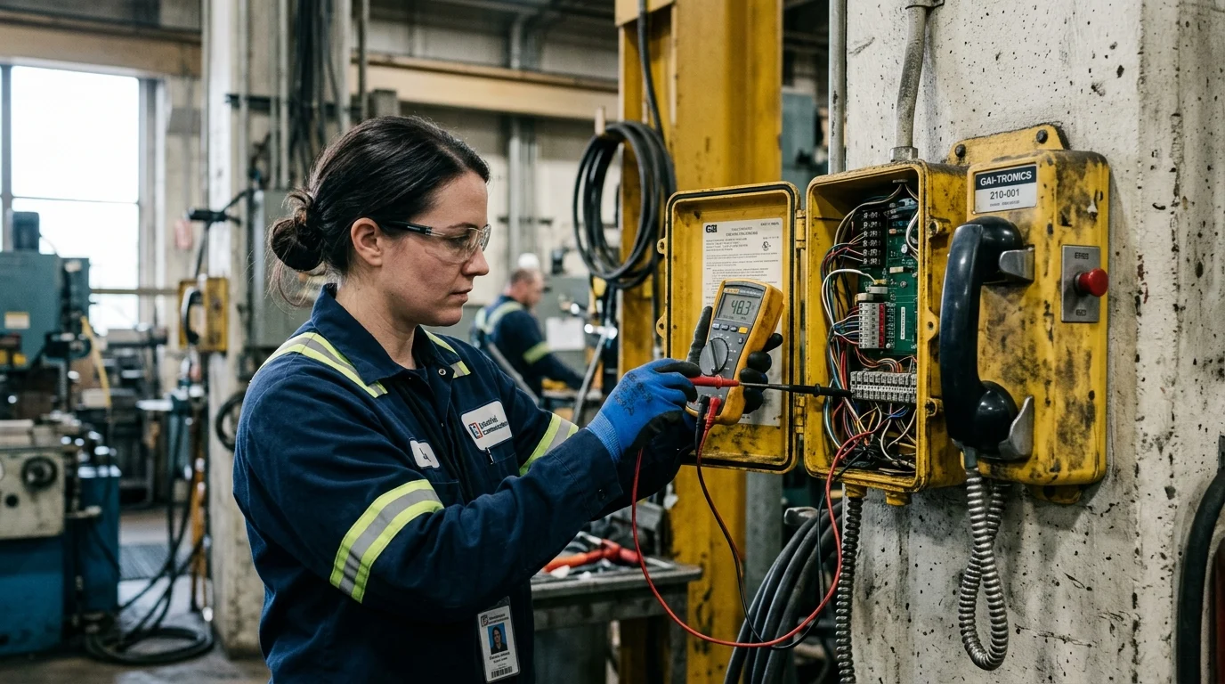
What tests confirm power, cabling, and signal issues
Electrical verification requires precise multimeter readings at the terminal block. For analog systems, confirm the off-hook loop current falls within the operational range of 20mA to 25mA; currents below this threshold will result in dropped calls or inaudible transmission. Cable continuity tests must show infinite resistance between conductors to rule out short circuits. For IP-based industrial phones, network cable certification tools should be utilized to test for near-end crosstalk (NEXT) and verify that the Category 5e/6 cabling meets the 100-meter maximum length limitation for stable PoE and data transmission.
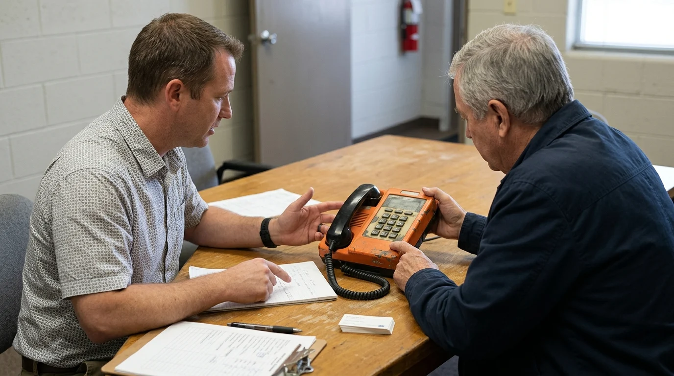
When to repair, recalibrate, or replace components
Deciding between component repair, recalibration, or full replacement depends on the severity of degradation and the criticality of the phone’s location. Minor issues, such as a misaligned hook switch or a loose terminal screw, require simple recalibration or tightening. However, if a printed circuit board (PCB) exhibits conformal coating failure with corrosion affecting more than 10% of the surface area, the entire board must be replaced to maintain operational reliability. Similarly, armored cables showing any breach in the stainless steel sheathing should be discarded entirely, as internal wire failure is imminent and cannot be reliably repaired.
Comparison criteria for diagnosis and prevention
Diagnostic parameters shift significantly depending on the communication protocol utilized and the environmental classification of the deployment area. Understanding these distinctions allows maintenance teams to deploy the correct diagnostic tools and interpret fault signatures accurately.
How analog and IP industrial phones differ
Analog and IP (VoIP) industrial telephones require divergent troubleshooting methodologies. Analog systems rely on continuous DC voltage and frequency-based signaling, making them susceptible to physical line degradation over long distances. IP phones utilize packet-switched data and PoE, requiring network analysis tools to diagnose latency, jitter, or SIP registration failures.
| Feature | Analog Industrial Phone | IP (VoIP) Industrial Phone |
|---|---|---|
| Power Source | Central office/PBX line voltage (48V DC) | Power over Ethernet (PoE, IEEE 802.3af/at) |
| Primary Diagnostic Tool | Multimeter, Butt Set | Network Cable Tester, Packet Sniffer |
| Distance Limitation | Up to 5 kilometers (dependent on wire gauge) | 100 meters (without active extension/switches) |
| Common Fault Source | High loop resistance, EMI/RFI interference | IP address conflicts, network switch port misconfiguration |
What symptom-to-cause comparisons should include
Effective symptom-to-cause mapping reduces diagnostic time by correlating specific user complaints with highly probable technical faults. A comprehensive comparison matrix accounts for both analog and digital failure modes, providing technicians with a high-probability starting point for their investigations.
| Observed Symptom | High-Probability Cause | Recommended Verification |
|---|---|---|
| Persistent Static / Crackling | Moisture ingress at junctions, EMI | Check seal integrity; measure ground resistance (< 5Ω) |
| No Dial Tone (Analog) | Line break, PBX port failure | Measure tip/ring voltage (should be ~48V DC idle) |
| No Dial Tone (IP) | PoE failure, SIP authentication error | Verify switch port power output and VLAN tags |
| Low Earpiece Volume | Ferrous dust on receiver magnet | Inspect handset capsule; test line impedance |
Which enclosure and hazardous-area factors matter
Troubleshooting in hazardous locations governed by ATEX, IECEx, or Class I Division 1 standards introduces stringent procedural requirements. Telephones in these zones utilize intrinsically safe circuits or explosion-proof enclosures. Technicians cannot open explosion-proof enclosures while the circuit is live without a hot work permit. Furthermore, when diagnosing intrinsically safe phones, the Zener barriers located in the safe area must be tested to ensure they are limiting voltage and current (typically capped below 30V and 100mA) correctly. Any degradation in these barriers can result in total signal loss, mimicking a telephone hardware failure.
How to reduce repeat failures
Transitioning from reactive troubleshooting to proactive lifecycle management significantly decreases the frequency of industrial telephone failures. Implementing structured maintenance and inventory protocols ensures sustained communication reliability across the facility.
What preventive maintenance practices work best
Effective preventive maintenance requires scheduled interventions tailored to the environmental severity. In highly corrosive or humid environments, internal desiccant packs should be replaced bi-annually to prevent microscopic condensation on sensitive PCBs. Technicians should perform torque verification on all enclosure bolts, ensuring they meet the manufacturer’s specified rating (often between 1.5 to 2.5 Nm) to maintain IP66/IP67 ingress protection. Additionally, conducting automated or manual acoustic loop tests every 90 days confirms both microphone and speaker functionality without requiring disassembly, identifying gradual acoustic degradation before it results in a total failure.
How to plan repairs, spares, and replacements
Strategic spare parts management is critical for minimizing mean time to repair (MTTR). Facilities should maintain a localized spare parts inventory based on the Mean Time Between Failures (MTBF) of specific components. A standard industry benchmark is to hold a 5% to 10% spare ratio for high-wear items such as armored handsets, magnetic hook switches, and replacement keypads. For mission-critical IP networks, keeping pre-configured, cold-standby telephone mainboards allows technicians to execute a board swap in under 15 minutes, restoring service immediately while the faulty unit is sent for bench diagnostics or RMA processing.
Key Takeaways
- The most important conclusions and rationale for Industrial telephone troubleshooting
- Specs, compliance, and risk checks worth validating before you commit
- Practical next steps and caveats readers can apply immediately
Frequently Asked Questions
What usually causes static noise on an industrial phone?
Static often comes from poor grounding, EMI from VFDs or motors, or moisture at terminals. Check earth resistance, inspect cable shielding, and reseal any wet or corroded junctions.
How can I confirm why there is no dial tone?
For analog phones, measure tip-ring voltage; on-hook should be about 48V DC. For VoIP models, verify PoE power, network link, and SIP registration status in the IP PBX.
Why is the call volume too low in a noisy plant area?
Low volume is commonly caused by corroded terminals, long cable runs, damaged handset cords, or worn speakers. Clean connections, test line impedance, and replace faulty handset or speaker parts if needed.
What should I inspect first on a Siniwo weatherproof or explosion-proof phone?
Start with external checks: cable glands, seals, handset cord, hook switch, and terminal corrosion. On Siniwo rugged units, restore enclosure sealing carefully after inspection to maintain IP protection.
When should I replace parts instead of continuing troubleshooting?
Replace components when testing shows broken handset cord conductors, failed speakers, persistent low insulation resistance, or unstable grounding after correction. In hazardous sites, use certified replacement parts matched to the phone model.
Post time: Jun-03-2026