
Why Accurate Fire Nozzle Flow Rate Testing Matters
Fireground hydraulics relies on empirical validation rather than theoretical assumptions. The discrepancy between an apparatus pump chart and the actual nozzle discharge can dictate the success or failure of an interior fire attack. Flow testing provides quantitative assurance that the attack package—comprising the pump, hose, and fire nozzle—delivers the expected gallons per minute (GPM). Under NFPA 1962 standards, fire departments are mandated to conduct annual testing of hoses and appliances, yet tactical flow testing on the fireground requires a deeper understanding of hydraulic variables to ensure suppression operations meet the required thermal threshold.
How flow accuracy affects attack line performance
The primary mechanism of fire suppression is cooling, which is directly proportional to water flow. A single gallon of water absorbs approximately 9,346 BTUs when fully converted to steam at 212°F (100°C). Consequently, an attack line successfully flowing 150 GPM yields a theoretical cooling capacity of over 1.4 million BTUs per minute. However, if unmeasured friction loss or nozzle defects reduce that flow to 115 GPM, the cooling capacity drops by nearly 330,000 BTUs per minute. This deficit directly impacts the attack team’s ability to overcome the heat release rate (HRR) of modern synthetic fuel loads, increasing the risk of thermal runaway or flashover.
Furthermore, flow accuracy directly dictates nozzle reaction forces. If an automatic nozzle requires 100 PSI to flow 150 GPM, the resulting nozzle reaction is approximately 76 pounds of force. Unintended flow variations can either leave the stream mechanically deficient or over-pressurize the line, physically exhausting the nozzle operator and reducing their operational endurance.
How to define target nozzle flow rates
Establishing target fire nozzle flow rates requires calculating the required fire flow (RFF) for the specific occupancy type, fire load, and tactical objective. The National Fire Academy (NFA) formula dictates that RFF equals the length multiplied by the width of the involved structure, divided by three, yielding the required GPM for a fully involved floor.
For standard residential deployments, a target flow rate of 150 to 160 GPM is widely accepted as the baseline for a 1.75-inch handline. Commercial occupancies, featuring higher ceilings, open floor plans, and denser fuel loads, necessitate 2.5-inch handlines with target flows ranging from 250 to 300 GPM. Defining these targets establishes the baseline for all subsequent flow testing. A fire department must formally adopt these target parameters before purchasing or testing nozzles, ensuring that the pump discharge pressure (PDP) charts are calibrated to deliver these exact specifications under field conditions.
Fire Nozzle Flow Variables to Measure Before Testing
Before initiating a flow test, operators must quantify the hydraulic variables that will influence the test outcome. A fire nozzle does not operate in isolation; it is the terminal component of a complex hydraulic system. Failure to account for hose specifications, elevation changes, and inline appliances will result in inaccurate test data and flawed tactical assumptions.
Nozzle specifications that determine expected flow
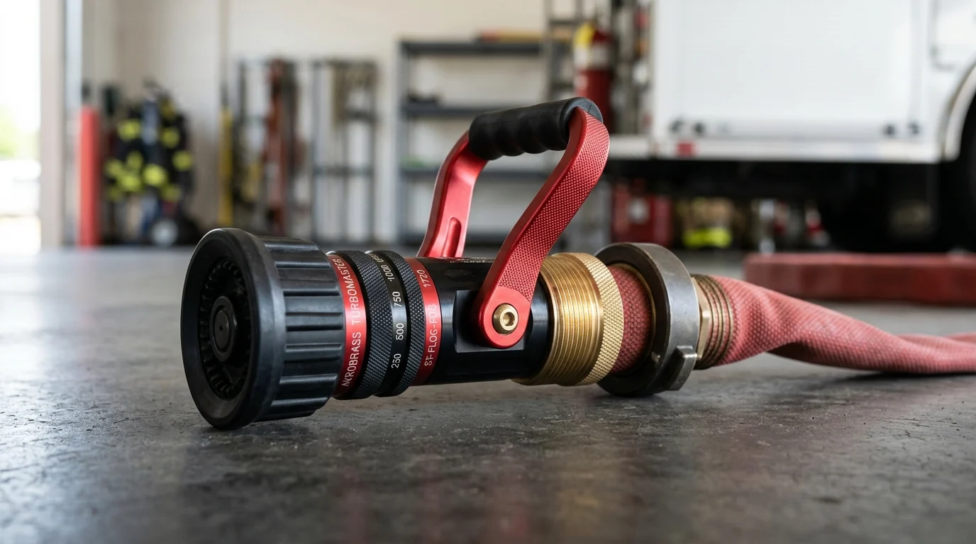
The manufacturer’s specifications dictate the expected flow rate at a specific operating pressure. A fixed-gallonage fog nozzle may be rated for 150 GPM at 50, 75, or 100 PSI nozzle pressure (NP). Automatic nozzles operate on a variable spring mechanism designed to maintain a relatively constant 100 PSI tip pressure across a flow range, typically 70 to 200 GPM. Smooth bore nozzles rely on the internal diameter of the tip and the discharge pressure, with standard handline operations modeled at 50 PSI NP.
Understanding the nozzle’s specific K-factor—a constant representing the discharge coefficient—is essential. The K-factor allows technicians to predict flow using the formula Q = K * sqrt(P). If the K-factor is unknown, or if the nozzle’s internal geometry has degraded due to abrasive wear, the expected flow will diverge significantly from the measured flow during the test.
Hose diameter, length, elevation, and appliance effects
The hose layout preceding the nozzle introduces friction loss (FL), the most variable component in fireground hydraulics. Friction loss is calculated using the standard formula FL = C * (Q/100)^2 * L, where C is the friction loss coefficient, Q is flow in GPM, and L is the hose length in hundreds of feet.
Modern lightweight attack hoses often feature different internal diameters (true ID) than legacy hoses, drastically altering the C coefficient. For example, a modern 1.75-inch hose with a true ID of 1.88 inches might exhibit a friction loss of 35 PSI per 100 feet at 150 GPM, whereas older models might exceed 50 PSI at the same flow. Elevation also impacts the test environment; gravity exerts a pressure loss or gain of 0.434 PSI per foot of elevation, commonly rounded to 5 PSI per residential floor. Furthermore, inline appliances such as wyes, water thieves, or break-apart valves typically introduce an additional 10 to 25 PSI of friction loss depending on the total flow rate, which must be factored into the baseline pump discharge pressure before testing begins.
Smooth bore vs. fog nozzle flow comparisons
Comparing smooth bore and fog nozzles during flow testing requires standardizing the metrics. Smooth bore nozzles provide a solid stream with lower optimal operating pressures, reducing nozzle reaction for the operator. Fog nozzles, whether fixed, selectable, or automatic, rely on water breaking against a central baffle to create a specific pattern, generally requiring higher pressures to function optimally.
| Nozzle Type | Standard Operating Pressure (NP) | Typical Flow Range (1.75-inch Hose) | Nozzle Reaction at 150 GPM | Primary Variable Affecting Flow |
|---|---|---|---|---|
| Smooth Bore (7/8-inch Tip) | 50 PSI | 160 GPM | ~60 lbs | Tip Diameter, Pump Pressure |
| Fixed-Gallonage Fog | 50, 75, or 100 PSI | 150 – 200 GPM | ~60 – 76 lbs | Baffle Wear, Pump Pressure |
| Selectable-Gallonage Fog | 100 PSI | 30 – 200 GPM | Variable | Operator Selection, Debris |
| Automatic Fog | 100 PSI | 70 – 200 GPM | Variable (up to 85 lbs) | Spring Tension, Pump Pressure |
During flow testing, automatic nozzles often mask inadequate pump pressures by maintaining a visually acceptable stream reach while secretly sacrificing GPM. Because the internal spring adjusts the baffle to maintain tip pressure, a drop in pump pressure simply reduces the orifice size, lowering the flow without collapsing the stream. Smooth bore nozzles, conversely, exhibit a visually degraded, drooping stream when under-pressurized, providing immediate visual feedback before the flow meter confirms the deficit.
How to Test Fire Nozzle Flow Rate Accurately
Executing an accurate fire nozzle flow test requires rigorous methodology, calibrated instrumentation, and controlled environmental conditions. Field expedience must be balanced with scientific accuracy to ensure the resulting data can safely dictate fireground pump operations and pre-incident planning.
Step-by-step flow test procedure
The step-by-step procedure begins with establishing a continuous, reliable water supply, preferably drafted from a static source or supplied by a high-volume municipal hydrant to prevent intake pressure fluctuations. The hose layout must be deployed linearly with minimal kinks or sharp bends to isolate friction loss to the hose jacket itself.
The pump operator throttles the apparatus to the target Pump Discharge Pressure (PDP) calculated for the specific layout. Once the line is charged, the nozzle operator opens the bale fully to bleed all trapped air and clear any initial debris. The system must run at a steady state for a minimum of 45 to 60 seconds to allow the pump governor and inline hydraulics to stabilize. Only after stabilization should the flow readings be captured. Multiple runs should be conducted—typically three iterations per nozzle—to average out transient pressure spikes and ensure repeatability.
Using pitot gauges, inline flow meters, and pump gauges
Accurate measurement relies on selecting the appropriate instrumentation. Pitot gauges are the gold standard for testing smooth bore nozzles. The blade is inserted into the center of the solid stream, at a distance of half the tip diameter from the orifice. The pressure reading is then converted to flow using the formula Q = 29.83 * c * d^2 * sqrt(p), where ‘c’ is the coefficient of discharge (usually 0.99 for smooth bores), ‘d’ is the tip diameter, and ‘p’ is the pitot pressure.
For fog nozzles, where pitot gauges cannot be used due to the broken stream, inline flow meters are mandatory. Modern electromagnetic inline flow meters provide a high degree of accuracy, typically +/- 1% to 3% of the reading, without introducing additional friction loss. Paddlewheel flow meters are also common but require periodic calibration to prevent mineral buildup from skewing the rotational speed. Relying solely on the fire apparatus’s onboard flow meters or discharge gauges is highly discouraged for baseline testing, as pump panel gauges frequently fall out of calibration by 10% or more due to continuous fireground vibration.
How to record nozzle flow readings
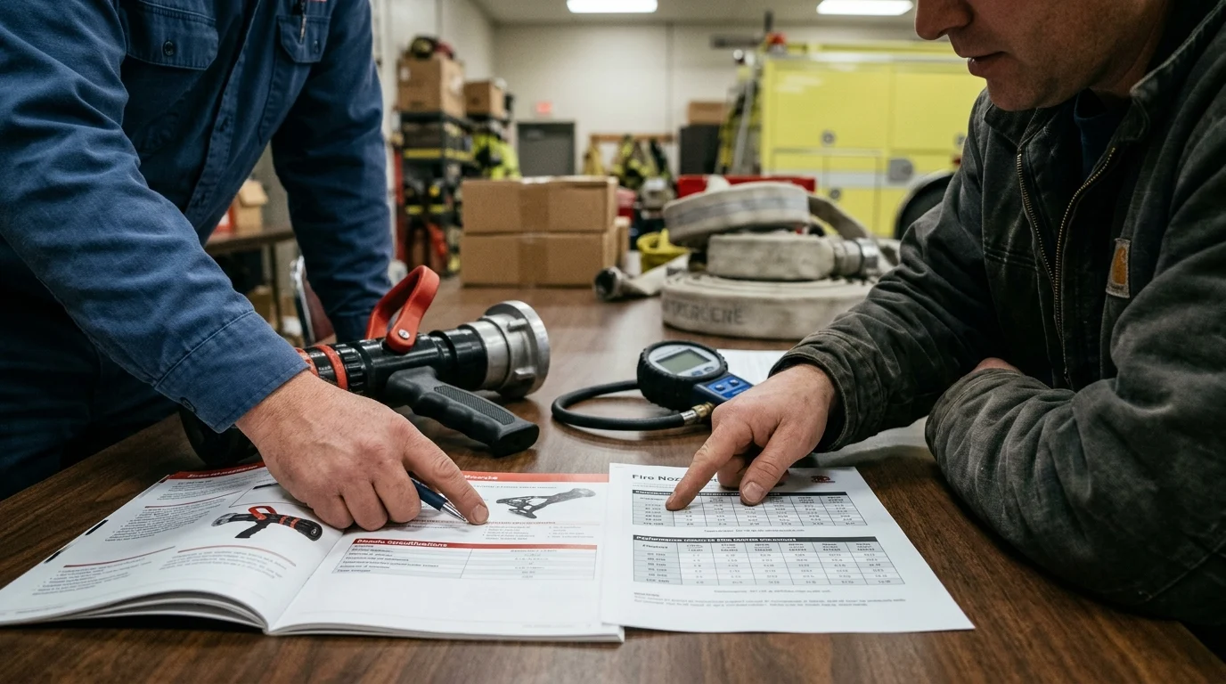
Data logging during the test must be meticulous to ensure valid longitudinal analysis. Operators must record the exact time of day, the specific apparatus used, the hose manufacturer and age, the nozzle serial number, the target PDP, the actual PDP, the inline flow meter reading (GPM), and the pitot or nozzle pressure (NP).
Utilizing a standardized spreadsheet or dedicated hydraulic testing software ensures that the data is structured efficiently. Technicians should capture a minimum of three data points per nozzle setting. For selectable-gallonage nozzles, readings must be recorded at every gallonage setting (e.g., 95, 125, 150, 200 GPM) to verify that the internal selector ring is engaging properly and delivering the rated flow at the specified pressure. Any anomalies, such as visible leaks at the swivel or stiffness in the bale, must be documented alongside the flow numbers.
How to Interpret Fire Nozzle Test Results
Once the empirical data is collected, the focus shifts to hydraulic analysis. Interpreting fire nozzle test results involves identifying discrepancies between theoretical pump charts and real-world performance, diagnosing the root causes of flow deficits, and optimizing the attack package for operational deployment.
Failure patterns caused by friction loss or equipment issues
Diagnosing flow failures requires systematic isolation of variables. A lower-than-expected flow rate is typically caused by excessive friction loss in the hose, a malfunctioning pump discharge valve, or an internal obstruction in the nozzle.
| Symptom / Test Result | Probable Cause | Diagnostic Action | Required Intervention |
|---|---|---|---|
| Flow >15% below target; NP is correct | Tip diameter worn (smooth bore) or baffle damaged (fog) | Measure tip with calipers; inspect baffle | Replace tip or rebuild nozzle core |
| Flow >15% below target; NP is low | Excessive friction loss in hose layout | Insert inline gauge behind nozzle to check NP | Recalculate pump chart for higher FL |
| Flow fluctuates wildly (+/- 20 GPM) | Debris in stream shaper or paddlewheel meter | Inspect inline meter and nozzle screen | Flush system; clean internal screens |
| High flow, extremely high nozzle reaction | Over-pressurization at the pump | Check pump panel discharge gauge calibration | Calibrate pump gauges; lower PDP |
In automatic nozzles, a common failure pattern is spring fatigue. Over years of service, the internal spring loses tension, causing the baffle to open prematurely at lower pressures. This results in the nozzle delivering a heavy, low-velocity stream that fails to achieve the necessary reach and penetration, even when the inline flow meter indicates the GPM is technically adequate. Recognizing these mechanical failure patterns is crucial for accurate interpretation.
When to Adjust, Retest, or Replace Fire Nozzles
The data derived from flow testing must drive actionable decisions regarding equipment maintenance, tactical operations, and capital expenditure. Testing is only valuable if the organization is willing to adjust its operational parameters, retest failed components, or execute a replacement strategy when equipment reaches the end of its lifecycle.
When to adjust pump pressure, hose layout, or nozzle settings
Adjustments are the most common outcome of a fireground flow test. If a nozzle underperforms due to unexpected hose friction loss, the immediate corrective action is to update the department’s pump charts. For instance, if a 200-foot crosslay requires 145 PSI PDP to achieve 150 GPM instead of the theoretical 130 PSI, the pump operator’s manual must reflect the new 145 PSI standard.
However, if adjusting the PDP pushes the nozzle reaction beyond the ergonomic threshold of 65 to 75 pounds for a single firefighter, tactical adjustments are necessary. The department may need to switch from a 100 PSI fog nozzle to a 50 PSI low-pressure fog or smooth bore nozzle to achieve the target GPM without exhausting the operator. Following any physical adjustment to the nozzle mechanism, such as tightening a loose baffle, lubricating the slide valve, or replacing a worn gasket, a mandatory retest must be conducted to verify that the flow rate has returned to the acceptable +/- 10% tolerance band.
Decision framework for nozzle replacement and procurement
When adjustments and repairs fail to correct flow deficits, a rigid decision framework for replacement must be activated. Nozzles subjected to harsh fireground environments have a finite operational lifespan, typically 10 to 15 years depending on maintenance frequency, water quality, and deployment volume. If a nozzle fails its flow test by more than 10% and a certified technician determines that the internal wear cannot be remedied with a standard rebuild kit (which usually costs $50 to $150), replacement is mandatory.
Procurement officers must factor in the current cost bands for professional-grade fire nozzles, which generally range from $600 to $1,200 per unit for standard handlines, and up to $2,500 for specialized master stream devices. Additionally, procurement timelines must be managed; custom-machined nozzles or specific thread configurations can carry lead times of 4 to 8 weeks. Establishing a minimum order quantity (MOQ) for fleet replacement can often secure volumetric discounts, allowing a department to transition an entire battalion to a new, flow-tested nozzle standard simultaneously, thereby ensuring uniform hydraulic performance across all response apparatus.
Frequently Asked Questions
Why should crews verify actual fire nozzle flow instead of relying on pump charts?
Pump charts are starting points, not proof. Hose friction loss, appliance restrictions, elevation, kinks, and nozzle condition can reduce actual GPM, affecting cooling capacity, stream reach, and crew safety.
What is a common target flow for a 1.75-inch attack line?
Many departments use 150 to 160 GPM as a residential baseline for a 1.75-inch handline, but the final target should match the occupancy, fire load, hose package, nozzle type, and department tactics.
How often should hose and appliance testing be performed?
NFPA 1962 requires annual testing of fire hose and appliances. Departments should also conduct tactical flow tests after changing nozzles, hose loads, appliances, pump charts, or standard operating procedures.
Which variables should be recorded during a nozzle flow test?
Record nozzle model and pressure, hose diameter and length, pump discharge pressure, elevation change, inline appliances, measured GPM, stream quality, and nozzle reaction. These details make results repeatable.
Can an automatic fire nozzle give misleading flow results?
Yes. Automatic nozzles can maintain stream appearance across a pressure range, which may hide insufficient flow. Always confirm actual GPM with a calibrated flow meter, pitot method, or verified test setup.

Post time: Jun-22-2026